Two questions:
What can I due to eliminate/reduce router bit marks on bottom after cutting out pocket?
After cutting a a profile (oval shape) how can I go back and do a round over edge? (need bit and tool path type)?
Thanks
Joe
Tools Paths
-
JMOlshefski
- Vectric Apprentice
- Posts: 83
- Joined: Sat Nov 22, 2014 11:32 pm
- Model of CNC Machine: CNC Shark II
-
Rcnewcomb

- Vectric Archimage
- Posts: 5927
- Joined: Fri Nov 04, 2005 5:54 am
- Model of CNC Machine: 24x36 GCnC/WinCNC with ATC
- Location: San Jose, California, USA
- Contact:
Re: Tools Paths
It depends on the cause.What can I due to eliminate/reduce router bit marks on bottom after cutting out pocket?
Your spindle/router may be slightly out of plumb
One tip of the tool is damaged
Bottom clearance or lack of on the tool
Too fast rpm's causing the chips to be recut
Tool design - bits with a fishtail shape have good edge quality but may leave swirl marks on the bottom, consider an Onsrud 66-300 series bit, or some other bit with a slight radius on the corners

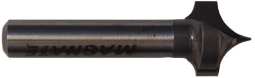
Use a roundover bit and a profile toolpath -- usually ON the vector and the depth should be the radius of the roundover.After cutting a a profile (oval shape) how can I go back and do a round over edge? (need bit and tool path type)?
But often this is after and easier to do on a router table using a roundover bit with a bearing. Do NOT use bits with a bearing on your CNC.
- Randall Newcomb
10 fingers in, 10 fingers out, another good day in the shop
10 fingers in, 10 fingers out, another good day in the shop
-
JMOlshefski
- Vectric Apprentice
- Posts: 83
- Joined: Sat Nov 22, 2014 11:32 pm
- Model of CNC Machine: CNC Shark II
Re: Tools Paths
Thanks, I will try a new bit, but how would I determine if my router was out of plumb?
-
Rcnewcomb
- Vectric Archimage
- Posts: 5927
- Joined: Fri Nov 04, 2005 5:54 am
- Model of CNC Machine: 24x36 GCnC/WinCNC with ATC
- Location: San Jose, California, USA
- Contact:
Re: Tools Paths
treischl provided this handy guide:how would I determine if my router was out of plumb?
The absolute easiest and cheapest way I know to tram a spindle is to:
1) Never mind that the plane of your spoil board or bed of your machine is not perpendicular to the spindle of your router. Take a skim cut of the entire surface as long as it will not be ridiculously out of whack.
2) Find a piece of 1/4 rod and bend a double "L" shape, so that end goes in the collet and the other end points at the bed of your machine. The horizontal leg between the two ends should be substantial, I usually use about 6 inches, you can try something a bit longer, but it might get too springy.
3) Now find a piece of material, metal works best that will bridge the highs and lows of your skim cuts, this is your "feeler" gage.
4) Put the rod in the collet and tighten it up. I suggest you unplug the router while you are doing these tests.
5) Now turn the collet by hand. You will be able to easily see the tilt of the router right to left and front to back by lowering it and checking it with the feeler gage.
Really sophisticated people use a dial indicator to do this setup, but a feeler gage is also really accurate. This is the same method used to square up a table on a drill press. Trying to use a square on a pin in a collet is hit and miss at best.
That is how I would tram it.
I would then make the adjustments at the mechanical connection points of the machine members. Example, where the Y carriage meets the X carriage, usually two places, but sometimes only one.
Or you may decide to adjust the spindle mount to accomodate on degree of tilt and then adjust the other tilt at a mechanical connection point.
- Randall Newcomb
10 fingers in, 10 fingers out, another good day in the shop
10 fingers in, 10 fingers out, another good day in the shop
-
TReischl

- Vectric Wizard
- Posts: 4657
- Joined: Thu Jan 18, 2007 6:04 pm
- Model of CNC Machine: 8020 48X36X7 RP 2022 UCCNC Screenset
- Location: Leland NC
Re: Tools Paths
There are some pricey off the shelf rigs to do what I wrote about above with dial indicators, anodized aluminum bars, etc. I am thinking the last one I saw was well over $100.
IMHO they are a total waste of money. The rod method works really good because of the proportions.
Here is how to think about it:
1/2 end mill. The edge of it is .25 from the center line of the spindle. The measuring point on the bent rod is 6 inches away.
The ratio is 24:1. So to get within .001 the gap on the rod would be .024. .0001 would be .0024. That is easily felt with a feeler gage.
The bigger issue is being able to adjust the machine. The last time I did it on mine it took a couple of hours of tinkering.
There is a caveat though. . . .if you run smaller cutters like .125 and below you may still get marks because smaller bits can deflect. If you run into that the best solution I have found is to leave a few thousandths for a finish pass. It is especially noticeable in aluminum.
"If you see a good fight, get in it." Dr. Vernon Johns