Get in the habit if creating a component that is the same size as your material. The component can have a thickness of 0.
Details:
Identifying and eliminating software generated chatter marks:
James Booth and Mark have talked about this in the past, but I thought I'd remind others of the steps to identify and eliminate software generated chatter marks.
Imagine that you are creating a plaque that has an oval dish as part of the design. For example:
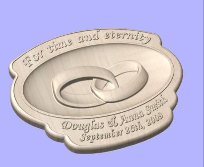
While doing the design I ran into an issue with software generated chatter on the border. Brian reminded me of the cure. I recall that James mentions this in his training videos.
So here is a refresher for those like me who have forgotten the cause and the cure of software generated chatter marks. I'll show the problem as well as the solution.
How to Create the Problem
1. Create a new project that is 24x18x1.25
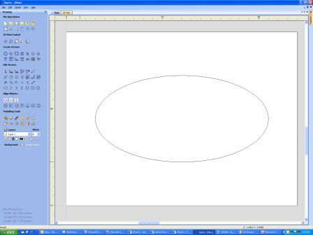
2. Draw an ellipse 18x9 and center it in the project
3. Choose the "Create Shapes from Vectors" tool
4. Choose a Dome shape with an angle of -85°, Scale to Exact Height of 1"
5. Make this into a component and close the Create Shape tool
6. Switch to the toolpaths tab
7. Select Create Finish Toolpath (the ellipse should still be selected)
8. Calculate a toolpath with a 0.25" ballnose at 8% stepover, raster strategy
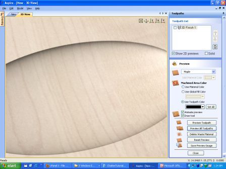
9. Preview the toolpath
10. Zoom into the top of the ellipse and note the "chatter" marks.
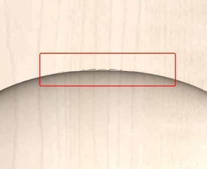
So what is causing the "chatter" to appear near the edge of the 3D machining boundary? Brian described the problem this way: Some of the near to edge points on the dish are below zero, as there are no points outside the dish, the tool can go a little lower at these points. A 'transparent' point is limited in height to the base of the material, so in effect you have a sharp vertical wall outside your dish. To cure the problem just model a plane for the material surface to subtract the dish from - this will ensure that the tool forms a clean edge at the material surface.
Allow me to paraphrase:
Imagine the router bit is like an ancient mariner sailing the known 3D world that was
defined by the ellipse. Beyond the ellipse is an area labeled "Here there be dragons".
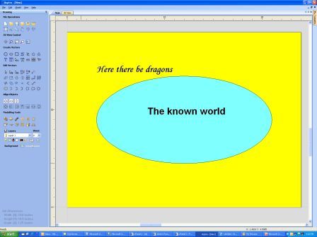
If the router bit sails too close to the edge it may fall off of the edge of the 3D world. The chatter is caused because the router bit isn't sure where to move since it has fallen off of the 3D world.
The Solution
The solution is to create a 3D plane that extends beyond the edge of the ellipse dish being carved. For example:
1) When creating a new project the first thing to do is create a rectangle the same size as the project.
2) With the rectangle selected choose the "Create Shapes from Vectors" tool
3) Choose the flat profile with a base height of 0.0
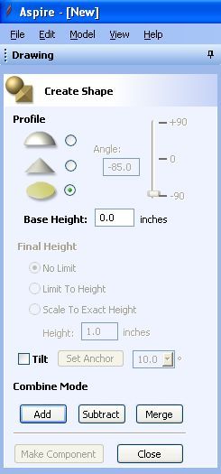
4) Click Add
5) Make this into a component and close the Create Shape tool
Now create the ellipse and the dish component. This time when you generate the 3D toolpath you will not see the chatter marks that were visible before.