Hi folks. Hopefully I can get some assistance or pointers on 3D carving since I am new to it. I've watched a few vectric tutorials on 3D carving, so I know the basics. I've done a couple of Michael's Weathervane Rooster clock project and after analyzing his awesome project, I've learned a bit more, which gave me an idea to do more of my own. I purchased a few 3D STL files from a guy on ebay. They all look really good and each have a moon in them. However, the moon is usually at a place which isn't good for a clock, so I use some editing software to remove the moon and place my own circle where I want the clock to be placed. I also smash it a bit since the 3D stl is always about 1.5" or more thick. And if the nose of the animal sticks out, the rest of the carving is too thin for comfort. Here is an example of a BEAR clock I am working on. Hopefully you can view it with no problem. I can't share the stl file because of license violations. Below is my question I need assistance, guidance or pointers from those of you that are experienced with 3D carving and Vcarve. Btw, I am using Vcarve Desktop 9.5 (latest version)
https://www.dropbox.com/s/gay62xe4ohdx8 ... e.jpg?dl=0
When I set up the rough cut using a .25" EM the program estimates around 5 hours of carve. Since I have a chinese 6040 with a 1.5kw spindle I can't use high speeds like some of you. With a .2" dept cut, I can't comfortably go higher than 30 in/min speed. So that is my comfort speed and depth. With these settings, I usually can do the job in half the time vcarve estimates. However, yesterday I decided to start this rough carve. I watched the preview toolpath and slowed it down a notch so I could see how many runs it would take. It showed 4 runs. BUT as I am standing there with the shopvac watching it carve... the first three passes were ok cuts... they each took around 30 to 45 minutes to cut. That is a lot of standing for an old guy like me w/ bad back & legs... but I managed. However, my problem is the last pass. It cut a small portion on the right side and cut AIR throughout the whole design until it got to the last run on the left side. Very frustrating. Is there a way to tell the toolpath to quit cutting air if there is nothing to cut? Perhaps not, but I must ask if there is a way. It obviously knows there is nothing there since it is going up & down over the previous carve.
Sorry to ramble, but I wanted to make sure I was somewhat clear. Thanks in advance for any help.
~ Ed
Help 3D rough cut of STL - Air Cutting
-
TReischl

- Vectric Wizard
- Posts: 4652
- Joined: Thu Jan 18, 2007 6:04 pm
- Model of CNC Machine: 8020 48X36X7 RP 2022 UCCNC Screenset
- Location: Leland NC
Re: Help 3D rough cut of STL - Air Cutting
Ed, it takes some manual work to control the roughing. I wish the software was "smart" enough to know where it has already reached final depth and not keep going over and over and over the same cut areas
In your case I would create a vector that encompasses the actual bear. It does not have to be perfect, just somewhat outside the bear and log. There will still be some air cutting but nowhere near as bad. Then I would use the pocket strategy to machine the clock face out.
There are other methods that work but they are pretty involved.
I have a fast machine but that is not the cure by any means. Sure, when I am doing something small I don't worry about the air cutting time. But when I do something larger it can easily add several hours to the cutting time. So we all have the same problem, just a matter of scale.
The other methods I mentioned usually involve creating "rings" . A simple example would be a full round moon, think convex dish shape. Define a series of concentric rings, then select a pair of rings and do the rough machining, select the next pair and repeat, wash, rinse, repeat. It takes more programming time but it saves a huge amount of cutting time. I do that a lot when I do vcarving on platter. Before the vcarving the platter needs to be cut to finish dimensions. On a 14 inch platter I save about an hour of cutting time.
"If you see a good fight, get in it." Dr. Vernon Johns
-
adze_cnc

- Vectric Wizard
- Posts: 4373
- Joined: Sat Jul 27, 2013 10:08 pm
- Model of CNC Machine: AXYZ 4008
- Location: Vancouver, BC, Canada
Re: Help 3D rough cut of STL - Air Cutting
For your roughing cut's "Roughing Strategy" are you using "Z Level" or "3D Raster"?
-
ezurick
Re: Help 3D rough cut of STL - Air Cutting
Thanks again Ted. I had already changed the vector around the moon so I pocket it out separately. That decreased the roughing time quite a bit. The other parts you explain is a bit above my level. I'll keep at it and try to figure things out.TReischl wrote:Ed, it takes some manual work to control the roughing. I wish the software was "smart" enough to know where it has already reached final depth and not keep going over and over and over the same cut areas
In your case I would create a vector that encompasses the actual bear. It does not have to be perfect, just somewhat outside the bear and log. There will still be some air cutting but nowhere near as bad. Then I would use the pocket strategy to machine the clock face out.
There are other methods that work but they are pretty involved.
I have a fast machine but that is not the cure by any means. Sure, when I am doing something small I don't worry about the air cutting time. But when I do something larger it can easily add several hours to the cutting time. So we all have the same problem, just a matter of scale.
The other methods I mentioned usually involve creating "rings" . A simple example would be a full round moon, think convex dish shape. Define a series of concentric rings, then select a pair of rings and do the rough machining, select the next pair and repeat, wash, rinse, repeat. It takes more programming time but it saves a huge amount of cutting time. I do that a lot when I do vcarving on platter. Before the vcarving the platter needs to be cut to finish dimensions. On a 14 inch platter I save about an hour of cutting time.
Do you have any pointers for thickness? Yesterday I finally done the finish cut and I used a 1/4" ball nose instead of an 1/8" BN. That help reduce the finish time and looked just as nice as the small tool... but when it got done, I removed it from the machine so I could clean it up, but it is just so thin. As I stated previously, I pull the STL into a mesh editing software and squish because the designer has it really thick... but what is making up most of that thickness is the bear's nose. Should I perhaps keep squishing more?
-
ezurick
Re: Help 3D rough cut of STL - Air Cutting
adze_cnc wrote:For your roughing cut's "Roughing Strategy" are you using "Z Level" or "3D Raster"?
Oh Wow! I didn't think that made a difference. I had it set for the 3D Raster along Y and the program est. time was about 5:15 hours. I changed it to Z Level Raster X and it reduced to 2.26. That is a BIG difference and will help for future roughing. Thank you so much for that tip. But looking at both... why would that direction of cut make it less time. In fact I had thought it would increase the time since it now has to do an additional step of removing the edge for each pass... right?
Also, do you have any tips about thickness? See my explanation to Ted on the previous post. The nose of the bear is making it difficult to keep an overall thickness to the whole project. It is so thin that in order to be a wall clock, I'd have to glue a backing. I am new to all this... but I am pretty sure the problem is that nose... but I don't want to squish it too much as lose the details of the dear's face. When I import it into vcarve, I center, then reduce it to the size of my board (11.25 x 21) and theb at the bottom, zero plane position in model.. the slider is at half; but looking at the bear graphic, because it is so thick, a large percentage is under the board (board is .75) and only the nose is sticking out. I have to pull the slider nearly all the way down to get the body of the bear into the wood, which of course brings the nose out protruding... and I believe this is what is causing my project to be nearly paper thin on some areas. I am open to any help or tips. Squish it more?
-
ezurick
Re: Help 3D rough cut of STL - Air Cutting
Here is a picture of the final finish and cut out. You can see how thin it is. I am rather disappointed. You can see that I squished the nose in with an editor as best I can.. but that made no difference. It is just carving out too much and I don't know how to control that. Any help or tips?
https://www.dropbox.com/s/meszuem7qgcv3 ... 5.jpg?dl=0
https://www.dropbox.com/s/meszuem7qgcv3 ... 5.jpg?dl=0
-
ezurick
Re: Help 3D rough cut of STL - Air Cutting
No help I see....  All the vectric tutorials on importing 3D files are vectric 3D files... nothing on STL imports... guess I'll continue researching and keep trying. Rather frustrating.
-
martin54

- Vectric Archimage
- Posts: 7350
- Joined: Fri Nov 09, 2012 2:12 pm
- Model of CNC Machine: Gerber 48, Triac PC, Isel fixed gantry
- Location: Kirkcaldy, Scotland
Re: Help 3D rough cut of STL - Air Cutting
Give it a bit of timeezurick wrote:No help I see....
Sure someone will answer your questions but most on the forum are people just like yourself with other things to do.
I will have a look latter but justy in the door from my work & going to have my dinner before I do anything
Have you tried this tutorial??
https://support.vectric.com/tutorials/V ... ideo_id=89
-
TReischl
- Vectric Wizard
- Posts: 4652
- Joined: Thu Jan 18, 2007 6:04 pm
- Model of CNC Machine: 8020 48X36X7 RP 2022 UCCNC Screenset
- Location: Leland NC
Re: Help 3D rough cut of STL - Air Cutting
Ed: Some of those models on eBay are obviously designed to attract customers not necessarily cut well. Nothing looks better than some really deep 3D. I have cut quite a few of those models. Usually I wind up taking them apart and reworking them a lot. Particularly ones with lettering. They have the letters so tall they are bound to tear off.
The problem with them as you have discovered is that they are one piece stl files. I do not run VCarve so I do not know if you have the ability to cut models apart and then alter the thickness of various pieces and then smooth things up again. I do that in Aspire quite a lot.
The only other thing I can suggest is that you start with the thickest material you can that allows you to put a bit in the collet and cut to the required depth. Checked the specs on a 6040 and it looks like most of them have just under 3 inches of Z travel. Not sure what that really is after putting a collet in the spindle? If you had 2.5 left then you could machine 1 inch thick stock. 1 inch of tool sticking out, 1 inch of material and some breathing room in between.
Well, just remember, when the cnc bug has bitten you really bad and the infection is raging and you decide it is time for a new machine pay attention to the Z travel, more is better, a lot better! Lemme go look at that machine again, BRB. . . .I don't see any easy way of removing the decking and working between the rails. It looks like most of those machines have a ball screw right down the middle of the table. If you do decide to get a new machine, give some thought to building one so that YOU get to decide how much Z you will need. I have 10 inches of Z travel on mine for a reason, I put 4 inch thick stuff in a vise that sits 1 inch above the table. 10 inches sounds like a lot until you realize that at best you can only cut material that is less than half that number. Worse, some of them tell you that you have X inches of Z movement, but do not tell you that if you put a spoil on you will lose the thickness of the spoilboard.
"If you see a good fight, get in it." Dr. Vernon Johns
-
Rcnewcomb

- Vectric Archimage
- Posts: 5919
- Joined: Fri Nov 04, 2005 5:54 am
- Model of CNC Machine: 24x36 GCnC/WinCNC with ATC
- Location: San Jose, California, USA
- Contact:
Re: Help 3D rough cut of STL - Air Cutting
There are two primary reasons to use a 3D Roughing toolpath:
1. to avoid breaking your finishing tool on a plunge
2. to remove material that your finishing tool isn't long enough to remove
Knowing this it is possible to limit the areas that receive a roughing pass. You can greatly reduce the roughing time, or perhapes eliminate it completely, with some careful study. A few minutes in the design phase can save hours in the cutting phase.
Breaking a Finishing Tool on a Plunge
A finishing bit is most likely to break when plunges into to a new area. The finishing bit usually breaks within an inch of the plunge. (Ask me how I know) This is because there is load on the entire front half of the bit up to the depth of the plunge, and chips can only be evacuated behind the bit travel.
You can find if/when the finish toolpath will move to a new area by using the Run to Retract feature in the toolpath preview.
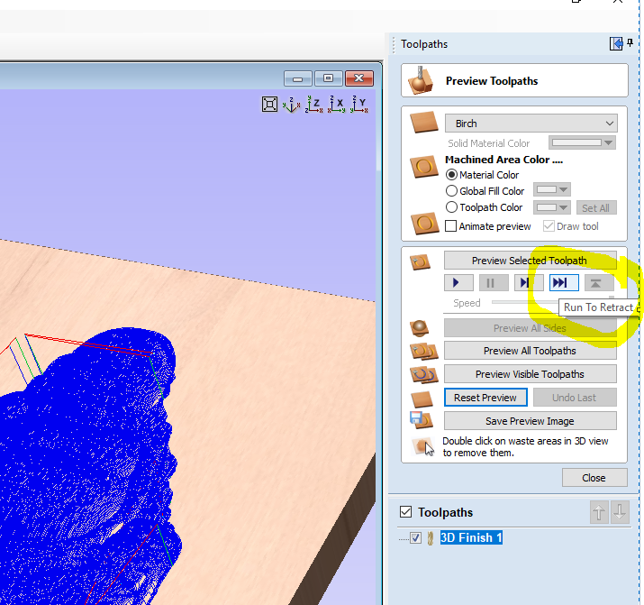
After it gets to a retract you can single-step until you can see where it plunged.
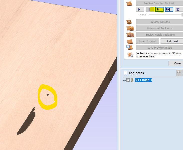
When you know those spots you can draw vectors around those areas and limit the roughing pass to just the areas where it will matter.
Finishing Tool Cutting Edge Length
The other reason for a roughing pass is to remove material that your finishing tool could not clear. For example, if I have a ballnose bit with a 0.5" cutting edge length, but my model has a maximum depth of 0.75", then I'd need the roughing toolpath to remove at least 0.25" of material in those deeper areas. Again, I can draw vectors to limit the roughing toolpath to thise areas.
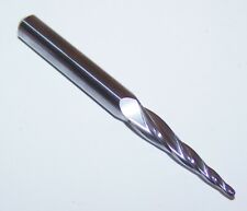
An alternate solution is to use a tapered ballnose bit with a long cutting edge length. This 1/16" tapered ballnose shown below has a 1" cutting edge. If I am using a 10% stepover on a 1/16" bit then the finishing toolpath is only removing a slice 0.00625" thick with each pass. This puts a very light load on the machine.
Dish Carvings
In a dish style carving (Style B) many people have discovered they can omit the roughing toolpath completely because the finishing toolpath starts at the edge at a very shallow level, moved gradually deeper towrds the middle, and then shallower as it approaches the other side.
1. to avoid breaking your finishing tool on a plunge
2. to remove material that your finishing tool isn't long enough to remove
Knowing this it is possible to limit the areas that receive a roughing pass. You can greatly reduce the roughing time, or perhapes eliminate it completely, with some careful study. A few minutes in the design phase can save hours in the cutting phase.
Breaking a Finishing Tool on a Plunge
A finishing bit is most likely to break when plunges into to a new area. The finishing bit usually breaks within an inch of the plunge. (Ask me how I know) This is because there is load on the entire front half of the bit up to the depth of the plunge, and chips can only be evacuated behind the bit travel.
You can find if/when the finish toolpath will move to a new area by using the Run to Retract feature in the toolpath preview.
After it gets to a retract you can single-step until you can see where it plunged.
When you know those spots you can draw vectors around those areas and limit the roughing pass to just the areas where it will matter.
Finishing Tool Cutting Edge Length
The other reason for a roughing pass is to remove material that your finishing tool could not clear. For example, if I have a ballnose bit with a 0.5" cutting edge length, but my model has a maximum depth of 0.75", then I'd need the roughing toolpath to remove at least 0.25" of material in those deeper areas. Again, I can draw vectors to limit the roughing toolpath to thise areas.
An alternate solution is to use a tapered ballnose bit with a long cutting edge length. This 1/16" tapered ballnose shown below has a 1" cutting edge. If I am using a 10% stepover on a 1/16" bit then the finishing toolpath is only removing a slice 0.00625" thick with each pass. This puts a very light load on the machine.
Dish Carvings
In a dish style carving (Style B) many people have discovered they can omit the roughing toolpath completely because the finishing toolpath starts at the edge at a very shallow level, moved gradually deeper towrds the middle, and then shallower as it approaches the other side.
The Design and Make models are optimized to "squish" more detail into the Z without adding extra Z height. Working with other models can be more challenging. If you frequently need to compress the Z without losing the detail Aspire has a feature called "Apply perspective along Z" which help keep the detail even as the Z height is reduced. With Vcarve you would need ot do this in another STL editor.I also smash it a bit since the 3D stl is always about 1.5" or more thick. And if the nose of the animal sticks out, the rest of the carving is too thin for comfort.
- Randall Newcomb
10 fingers in, 10 fingers out, another good day in the shop
10 fingers in, 10 fingers out, another good day in the shop
-
martin54
- Vectric Archimage
- Posts: 7350
- Joined: Fri Nov 09, 2012 2:12 pm
- Model of CNC Machine: Gerber 48, Triac PC, Isel fixed gantry
- Location: Kirkcaldy, Scotland
Re: Help 3D rough cut of STL - Air Cutting
As Ted has pretty much said if you are using vcarve then the thickness is pretty much the thickness & there is not much you can do without losing some of the detail, your options are make the whole project smaller which would reduce the z height, reduce the height of the model by using the scale z height tool n vcarve, edit the model in some other software, don't buy models with excessive z height or use thicker board stock.
As Ted has already said a lot of these models are made to attract people rather than cut well, a lot of them are also designed with 3D printing in mind rather than CNC work & the sellers will sell them for any purpose that makes them money, I personally buy very few stl files from ebay.
Not sure why you are not just using a thicker board though, most of the 3D work I do the thickness of my starting stock is dictated by the thickness of the model at the size I want the job to be rather than try & make the model fit the stock I have selected.
If you are trying to reduce the z height using the "Scale z Height" Tool then this is where the toolpath preview really comes in handy, you can reduce the height by a fraction & then run a toolpah to check the detail you will get, if it's still OK then you can reduce a fraction more & try again. keep doing that until you reach a point where you are not happy with the amount of detail you have lost & go back one step
-
ezurick
Re: Help 3D rough cut of STL - Air Cutting
That tutorial is also design & make 3D, not STL.martin54 wrote:Give it a bit of timeezurick wrote:No help I see....
Sure someone will answer your questions but most on the forum are people just like yourself with other things to do.
I will have a look latter but justy in the door from my work & going to have my dinner before I do anything
Have you tried this tutorial??
https://support.vectric.com/tutorials/V ... ideo_id=89
-
ezurick
Re: Help 3D rough cut of STL - Air Cutting
My 6040 Z travel is 4.7" and my spoil board is less than .75, so I should have plenty of Z travel room. Unfortunately I don't have any tools to handle thick boards. Guess I'll look into getting some though. When I do a 3D rough and finish, I can see the toolpath 3D results, but is there a way to see how deep any of the toolpath cut? Perhaps not. Also, I was trying to mimick Michael's Rooster Weathervane wall clock he recently posted as a free monthly project. That clock was a .75 thick board and it came out great. Of course he used vectric 3D files.
Ted suggested about the thickness of ebay STL files... how can one tell? Just by the pictures? This is the STL I purchased. I never thought to inquire about thickness. Is that a valid question to the designer?
Keep in mind that I haven't messed with any of them except the Bear and the Bison (as far as importing and carving). And both of them have big snouts.
-
ezurick
Re: Help 3D rough cut of STL - Air Cutting
Someone that used that same bear STL to make a wall clock. Perhaps it is the same person selling the STL files on ebay, I am not sure, but both are from Ukraine/Russia. Noticed that he got proper thickness. And perhaps he used a thicker board than what I am trying. Again, I will have to look into getting tools to handle thicker boards. My end mills couldn't do more than .75"
-
Adrian

- Vectric Archimage
- Posts: 14657
- Joined: Thu Nov 23, 2006 2:19 pm
- Model of CNC Machine: ShopBot PRS Alpha 96x48
- Location: Surrey, UK
Re: Help 3D rough cut of STL - Air Cutting
Maybe he's not using VCarve? Aspire has features for reducing the thickness of a 3D model without reducing the detail that VCarve doesn't.